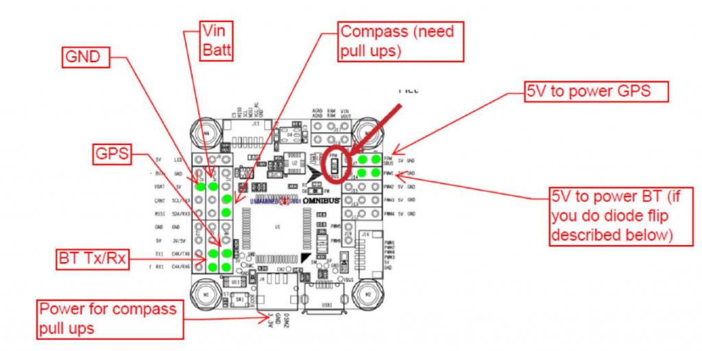
The OmniBusF4 boards are available on eBay for around 25USD. Go to www.ebay.com and search for “F4 V3 FC betaflight”. No need for the pro version, and this guide only applies to the standard version. Sometimes they can be hard to find. The board should look like the diagrams further down this page. The UBlox M8N GPS/compass will be a similar price. This should have 6 wires on two plugs.
First, let’s get Ardupilot on the board, and the board configured:
- Download and install Mission Planner (MP) https://ardupilot.org/planner/docs/mission-planner-installation.html
Note: Either Mission Planner or QGroundControl can be used to setup the FC board. All the documentation is going to show the use of Mission Planner, so I suggest you use the same. Later, for Bluetooth compass calibration, QGroundControl works great from an Android phone (Mission Planner is not available for Android).
- Install Ardupilot Firmware + bootloader – this can be a bit tricky. Just keep trying, eventually it will work! There are several other ways of doing this, but I have found using the SMT32 Cube Programmer the easiest:
- Now the board should work with mission planner – connect to MP (check you have the correct com port with device manager), and click on CONFIG, Full Parameter Tree, Load From File and open the attached .param file. Then ‘Write Params”
- So that should be the board configured.
You will need to learn something about Ardupilot to calibrate the gyros and compass.
REMEMBER: arming_required = 0 for logging to be active. For compass calibration (or any other time the board needs to be disarmed), set arming_required = 1
Next, set up to power the FC board
up to 2s lipo. Use a separate power supply from the Rx so the systems are isolated. I use a old 2s 900mAh LiFe. See the next picture for where to power the FC board.
Next Connect the GPS
- First configure the GPS in U-Center
The M8N GPS default baud rate is 9600 (or maybe 38400). You can use U-center to update this to 115200 and also 100ms rate. It is ok to leave the GPS on 9600 baud – just change the Ardupilot serial port configuration as appropriate. You connect to U-Center using a usb-uart converter, connected as shown. You may need to open up your GPS – most have different color wires….
GPS usb-uart FC Board
Black ground ground
Red Vcc (5V) 5V
Green is Tx connects to Rx Rx6
Yellow is Rx connects to Tx Tx6
Orange SCL SCL (compass)
White SDA SDA (compass)
- The GPS connects to Rx6/Tx6, SCL/SDA, and power on the FC board. I solder servo headers to the FC board (green dots), then use servo plugs on the GPS.
- But wait – the typical M8N does not have pull ups included for the I2C bus – so you also need to add pull up 1k (or 2.2k) resistors for compass i2c (I used the satellite Rx plug 3.3V for power here).
So that should get the GPS / Compass working.
Overall wiring looks like this:
Next sort the Blue Tooth (BT) connection
This step is optional, but it makes compass calibration with the GPS in the plane much easier.
Note that programming the BT board for 57,600 baud is sometimes a bit tricky… use Google!
The BT will be using 3.3v signal levels – the FC is probably 5v. I have had no issues, but something to check……
- The BT module needs to be configured using AT commands. Be sure nothing is paired to the BT module, connect it to your usb-uart adaptor, and connect to your PC. There are many different HC-05 modules out of china. Some have a button, some don’t. Google will help. But the main thing is to set the baud rate to 57,600 – often AT+BAUD7
But I have seen AT+BAUD1 required.
After changing the baud, change to usb-uart baud to 57600, and check sending AT results in OK
- I use one of the PWM headers to power the BT board. But to get 5V power on the PWM headers, you need to flip a diode around. The other option would be to power the BT using a Y lead from the GPS power supply. Anyway, this is the diode I flipped around – and with this done NEVER apply power @ the PWM headers:
- Now the BT can be wired like this:
BT FC Board
Ground GND
Positive 5V
Tx Rx1
Rx Tx1
Some Mission Planner Notes
- Serial 2 is shared with I2C. Because I2C is active, the serial parameters are ignored. They don’t need to be set to inhibit – this happens automatically.
- Remember you must do accelerometer calibration (this can be done on the bench). Remember to disarm the board – change arming required to 1. After calibration, change it back to 0.
- To calibrate the compass, change arming required to 1. After calibration, change it back to 0.
- Details on these calibration steps can be found here
Testing
- Plug in a microSD card (formatted FAT32)
- Have the FC outside, at ground level
- Plug in FC power (I use a 2s LiFe)
- Wait for the LED to stop fast flashing and become slower flashing (GPS acquired)
- Logging should now start
- Walk around with the FC board for a minute
- Unplug power
Now you should be able to use MP to view the log.


